
Mark III Detailed Breakdown Description
Pistol Parts Familiarization
Click image to enlarge picture
| Step #1 | Getting familiar with the outside of the pistol parts locations. |
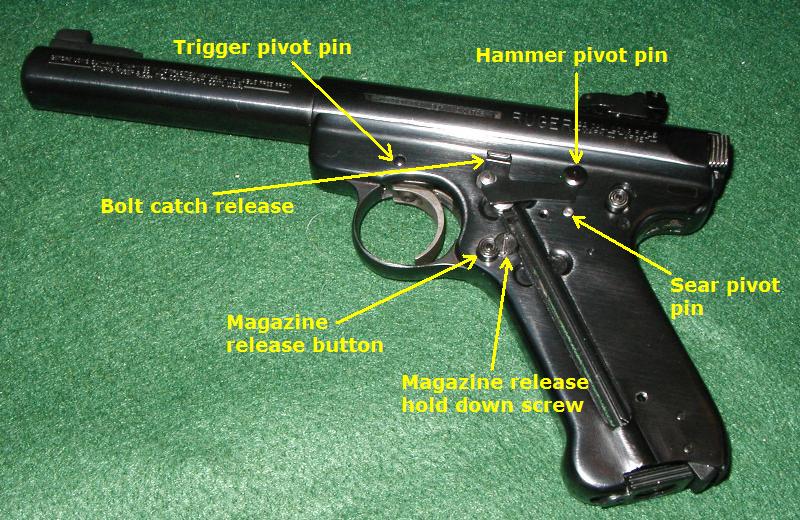 |
| Step #2 | The internal pistol parts locations. |
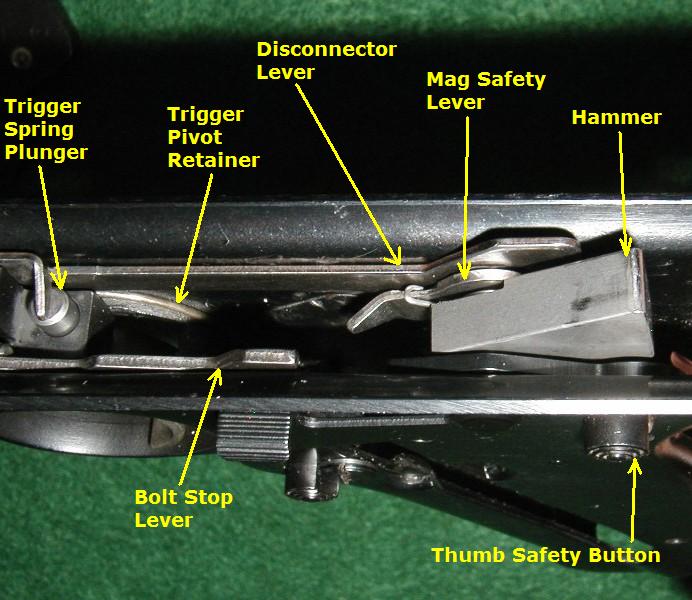 |
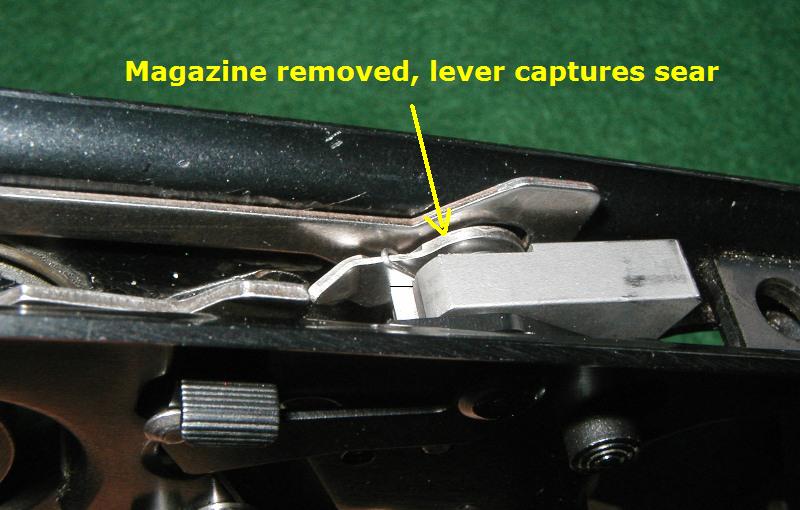
| Step #3 | The Mark III magazine safety disconnector lever, without a magazine installed. When there is no magazine installed, the disconnector safety hook captures the sear and prevents it from releasing the hammer. |
 |
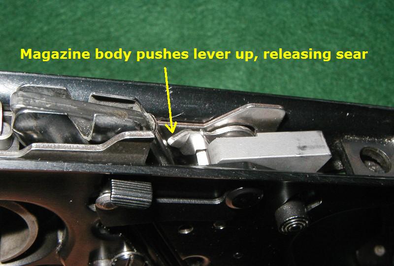
| Step #4 | The Mark III magazine safety disconnector lever, with a magazine installed. When a magazine is installed, the disconnector safety hook is pushed upwards by the magazine body, releasing the sear and allowing the hammer to release when the trigger is depressed. (Bolt stop lever is also raised higher by the empty magazine's follower button) |
 |
Trigger Group Operation
 |
 |
Copyright © Bullseye 2006,2007, Guntalk-Online.com, All rights reserved
Detailed Internal Frame Parts Removal
Click image to enlarge picture
| Step #1 | Field strip Mark III pistol following all proper precautions. Set grip frame up in a clean uncluttered work area. |
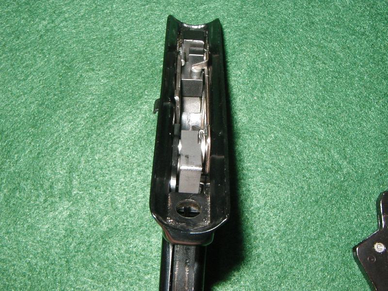 |
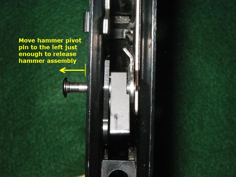
| Step #2 | Partially remove the hammer pivot pin to release the hammer from its location in the frame. Just slide the pin to the left far enough to release the hammer and magazine safety components. |
 |
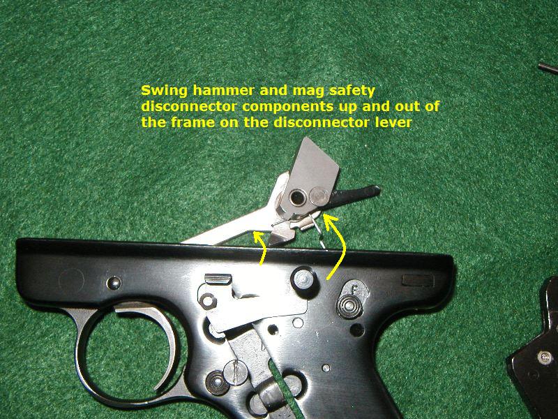
| Step #3 | Swing the hammer and magazine safety disconnector components up and out of the frame on the disconnector lever. |
 |
| Step #4 | Remove hammer and all of the magazine safety disconnector components from off the disconnector lever and set them aside. Hey! My Mark III mag disconnector doesn't look like that. If it looks like this one, it's OK, your's is just newer and installs the same. |
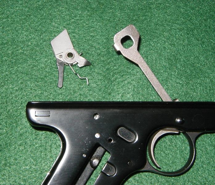 |
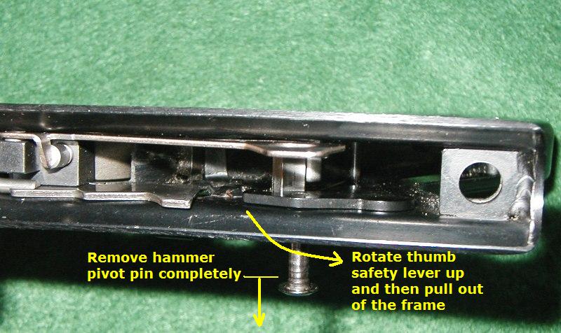
| Step #5 | Remove the hammer pivot pin completely from the grip frame. Next rotate the thumb safety lever upwards and pull out of the frame from the inside. Caution - take care not to lose the thumb safety detent ball and the detent ball spring. They have a tendency to fall out when you least expect it, and they're very hard to find. |
 |
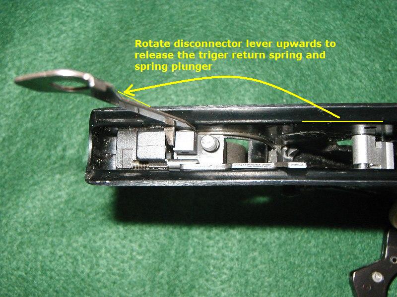
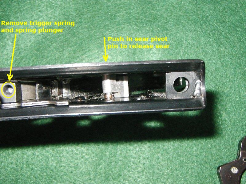
| Step #6 | Rotate disconnector lever up and remove the trigger spring plunger and trigger return spring, set them aside.
|
|
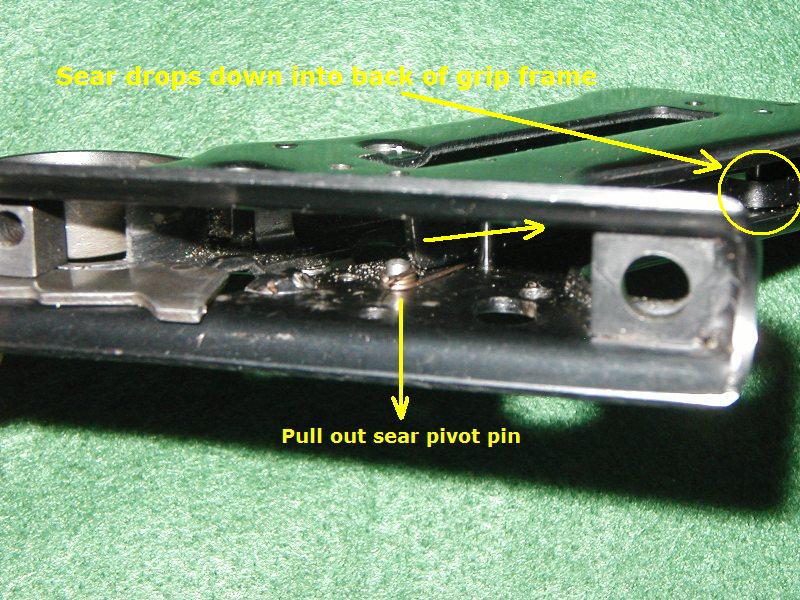
| Step #7 | Next, push in the sear pivot pin just far enough to let the sear drop into the back of the grip frame. Take care not to push the pin far enough to release the sear spring. |
 |
| Step #8 | After pushing the sear pivot pin in to the left, the sear will drop down into the bottom of the grip frame. Leave it there for now, you will recover it later.
|
|
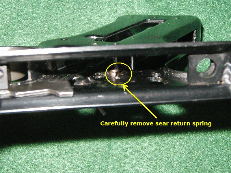
| Step #9 | Next, carefully remove the sear return spring and set it aside. After removing the sear return spring, turn the grip frame over and shake out the sear, set it aside. |
 |
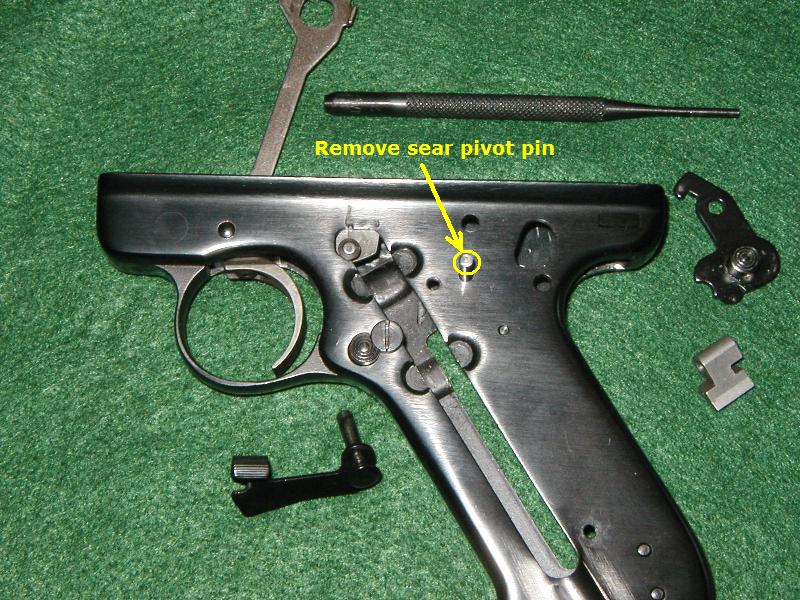
| Step #10 | Remove the sear pivot pin. Now all the Mark III rear grip frame internal parts have been removed. |
 |
Copyright © Bullseye 2006 - 2018, Guntalk-Online.com, All rights reserved
Detailed Internal Frame Parts Installation
Click image to enlarge picture
| Step #1 | Rotate grip frame so left side is facing downwards. Then place sear spring into frame. Orient the spring so the long leg is down and underneath the frame crosspin. The short spring leg should be oriented so it's facing upward and toward the rear of the frame. |
 |
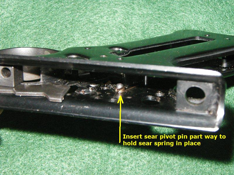
| Step #2 | Insert the sear pivot pin into the left hand side of the frame. Push the pin in just far enough to hold the spring in place. There should be a gap wide enough for the sear to fit into when it is put in its proper place. |
 |
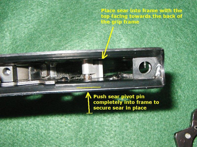
| Step #3 | Place the sear into the frame so the top is facing rearwards. Align the sear pin holes with the pivot pin and then push the pivot pin, left, through the sear and into the other side of the frame. Leave the sear facing rearwards for the moment. |
 |
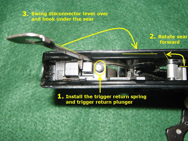
| Step #4 | First, install the trigger return spring and trigger return plunger. Next, rotate the sear forward. Last, swing the disconnector lever down and hook it under the right side of the sear. The disconnector lever will keep the sear in place and also prevent the trigger return plunger and spring from getting lost. |
 |
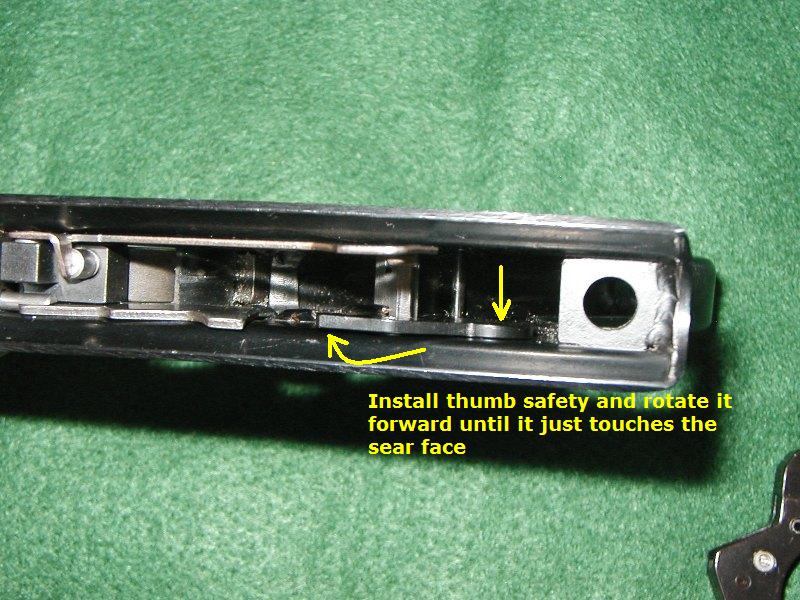
| Step #5 | Install the thumb safety lever through the center of the frame. Ensure the detent ball and spring are in place. Rotate the thumb safety forward until the hook just touches the sear face. |
 |
| Step #6 | Flip the pistol over onto its right side, install the bolt stop lever under the bolt stop pin and then align the rear portion with the hammer pivot pin hole. Insert the hammer pivot pin just enough to hold the bolt stop lever in place. |
 |
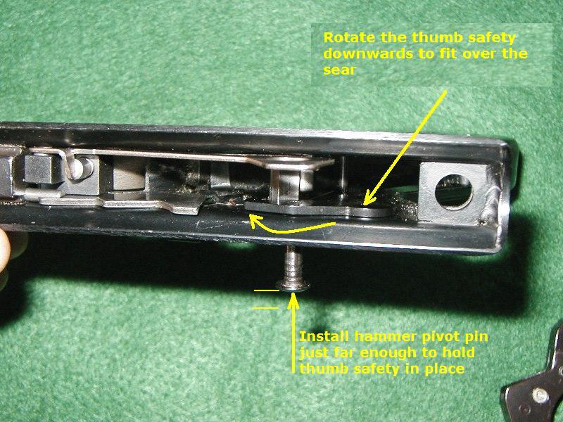
| Step #7 | Rotate the thumb safety forward until the hook fits over the sear face and the through hole aligns with the hammer pivot pin. Slide the hammer pivot pin in just far enough to hold the thumb safety and sear in place. Note - The pin head should be flush with the inside edge of the safety lever, leaving plenty of room for the hammer assembly when it gets installed in a few moments. |
 |
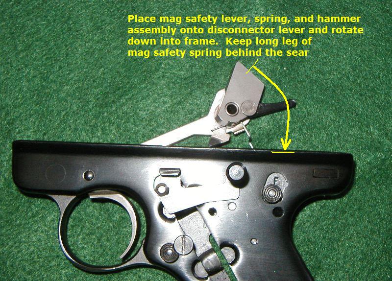
| Step #7 | Place the hammer assembly (Mark III magazine disconnector lever, lever spring, hammer bushing, and stepped hammer) onto the disconnector lever and swing the lever downwards into the frame. Position the long leg of the magazine disconnector lever behind the sear and place it down into the mainspring well. |
 |
| Step #8 | Align the hammer assembly with the frame holes and push the hammer pivot pin all the way to the right. The pivot pin should travel in far enough to sit flush on the right side of the frame. |
 |
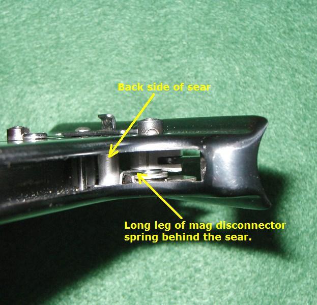
| Step #9 | This is the view from the mainspring well. The long leg of the magazine disconnector lever should be positioned behind the sear and in the mainspring well. |
 |
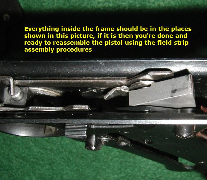
| Step #10 | Final inspection. Carefully inspect inside the grip frame and ensure all components are in the places shown in this picture. If they are, then you are ready to reassemble the pistol using the field strip reassembly procedures. There should be no spare parts. |
 |
Copyright © Bullseye 2006, 2007, Guntalk-Online.com, All rights reserved
Click image to enlarge picture
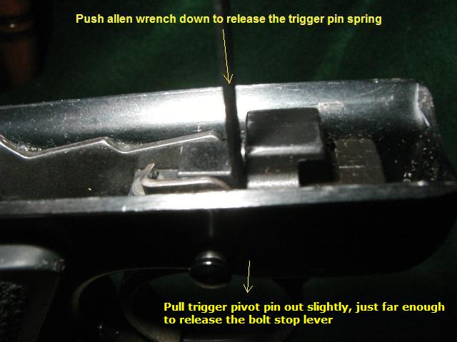
| Step #1 | Use a tool to push down trigger pin retainer spring. Pull the trigger pivot pin out to the right slightly. |
 |
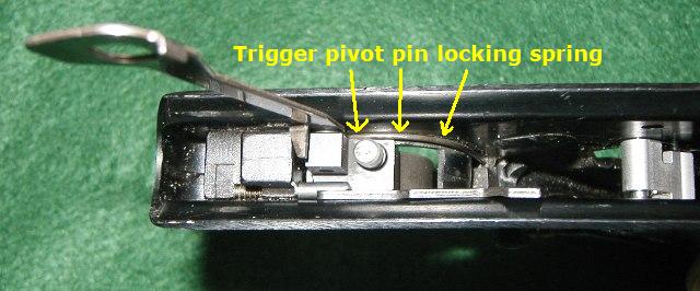
The trigger pivot pin locking spring is a piano type spring located on the right hand side of the trigger under the disconnector bar. |
 |
|
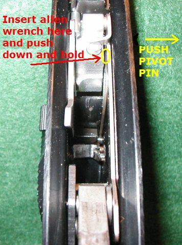
The location of the yellow circle shows where a small metal tool must be inserted to push down on the trigger pivot pin retaining spring. While pushing and holding the spring down, the triggger pivot pin must be pushed to the right. |
 |
|
| Step #2 | Use a tool to push bolt stop plunger forward in the frame, go far enough forward to release the bolt stop lever. |
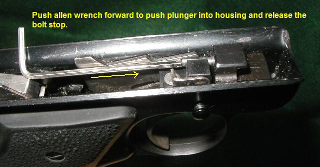 |
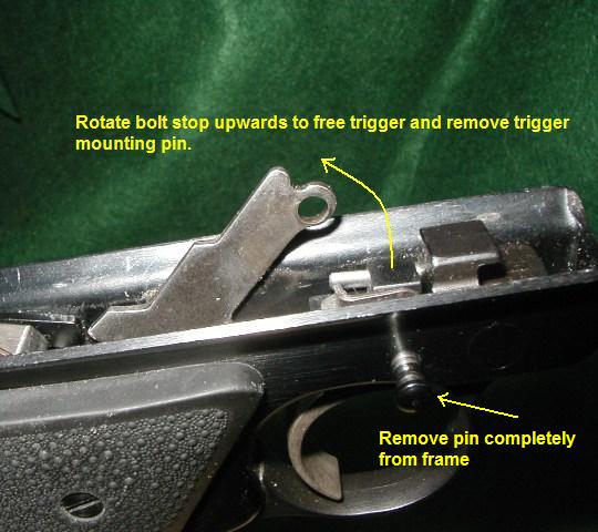
| Step #3 | Rotate front of the bolt stop lever upwards and out of the frame. Remove the trigger pivot pin completely. |
 |
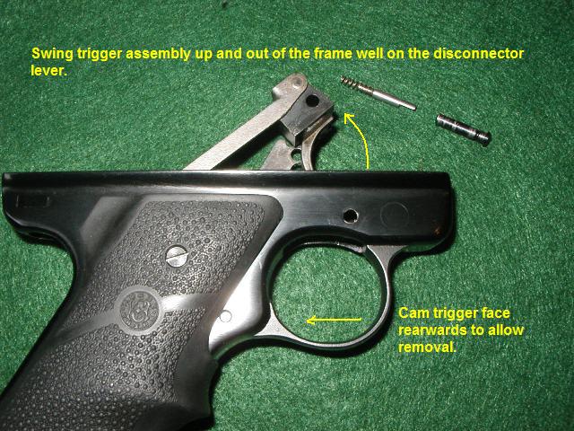
| Step #4 | Cam trigger backwards slightly and swing entire trigger assembly up and out of the trigger frame on the disconnector lever. Note - if the trigger you're removing has an overtravel stop in the face of the trigger then you may have to remove the hammer assembly to remove the trigger. Just remove the grips and follow the detailed strip procedures for removing the hammer. |
 |
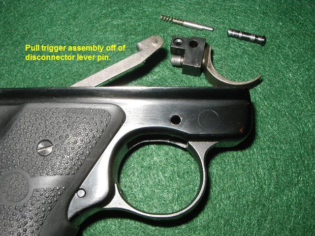
| Step #5 | Remove the trigger assembly from the disconnector lever by sliding it off of the disconnector pivot pin to the left. Trigger removal is complete. |
 |
| Step #6 | Reinstall the trigger assembly by following these directions in oppostite numerical order. |
Copyright © Bullseye 2006, 2007 Guntalk-Online.com, All rights reserved
Rear sight Removal
Click image to enlarge picture
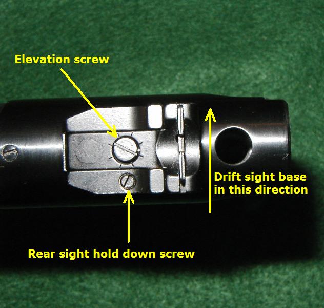
Step #1 |
Loosen the rear sight hold down screw with a small straight slotted screwdriver. Remove the screw completely from its hole. Add a few drops of penetrating oil to the hold down screw hole and let it settle into the sight mount. Clamp the receiver into a well padded vise. Use a brass punch and a medium sized hammer to drift the sight base off the receiver in the direction indicated by the arrow, from the left side of the receiver to the right (ejection port) side. |
 |
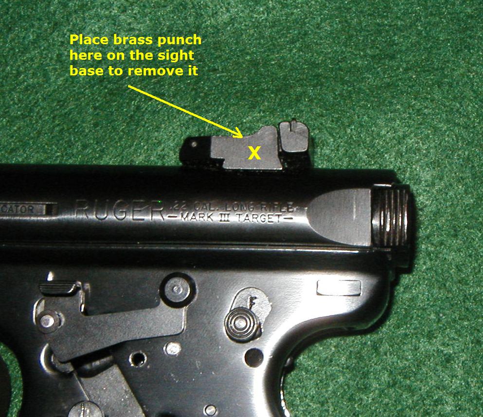
Step #2 |
This view shows where to place the punch for maximum energy transfer for drifting the base out of the Ruger's receiver. It may take some effort to get the base to start moving. Take care not to let the hammer slip and mar the finish of the pistol. Once the sight base begins to move, it will come out with several relatively light taps with the hammer. Reinstall the new base from the right (ejection port) side using the same methods described for removal. Tap the base over into position with several light taps using the brass punch and hammer. Degrease the sight hold down screw and hole. Replace the screw and add a little blue Locktite to the threads to secure it into place. |
 |
Copyright © Bullseye 2006, 2007 Guntalk-Online.com, All rights reserved
What triggers fit into a Mark III
Click image to enlarge picture
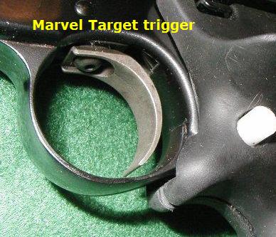
The Marvel Target trigger can be installed in the Mark III pistol. It has pretravel and overtravel screws installed in it from the manufacturer that are only internally adjustable. |
 |
|
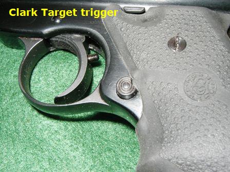
The Clark Target trigger can be installed into the Mark III pistol. It has a manufacturer installed overtravel screw that is externally adjustable. An internally adjustable pretravel screw can be installed into this trigger by the owner. |
 |
|
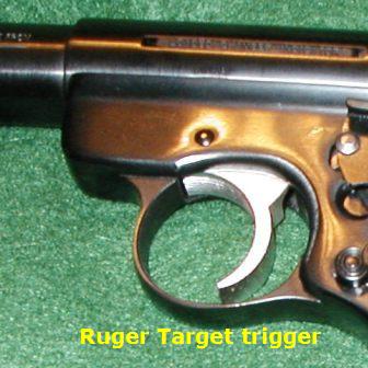
The factory Ruger Target trigger comes installed in this pistol. It has an internally adjustable overtravel screw in it. A internally adjustable pretravel screw can be installed in the trigger face by the owner |
 |
|
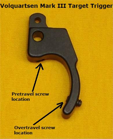
Volquartzen Mark III Target trigger. This trigger comes from the manufacturer with exterally adjustable pretravel and overtravel screws. The external shape of the trigger face has been curved slightly different to give the feel of a more straighter pull. Also the trigger width is much narrower than the older Mark II VQ Target trigger. |
 |
|
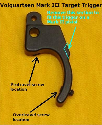
Any Trigger made for the Mark II pistol can be installed into the Mark III pistol. However not all triggers made for the Mark III pistol will install into a Mark II pistol without modification, because the trigger frame slot for a Mark III pistol is slightly longer than the earlier model pistols. The internal trigger well dimensions are identical between the Mark II and Mark III models. Currently there are some VQ Mark III target triggers that have the backside edge too long for installation into a Mark II. Cut or file the trigger where the line shows to resize it to fit into a Mark II pistol. |
 |
|
| If you have a 22/45 pistol and wish to install a Marvel trigger, they will workin most pistols without modification. However some 22/45 pistols will have a problem with the Marvel's blocky shape. One simple cut on the top front edge of the trigger block and you will have the clearance needed for the Marvel trigger to function properly in your pistol. | 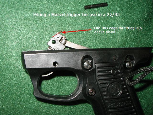 |
Copyright © Bullseye 2006, 2007, Guntalk-Online.com, All rights reserved
Click image to enlarge picture
Copyright © Bullseye 2006, 2007, Guntalk-Online.com, All rights reserved
Extractor Replacement /Reassembly
Click image to enlarge picture
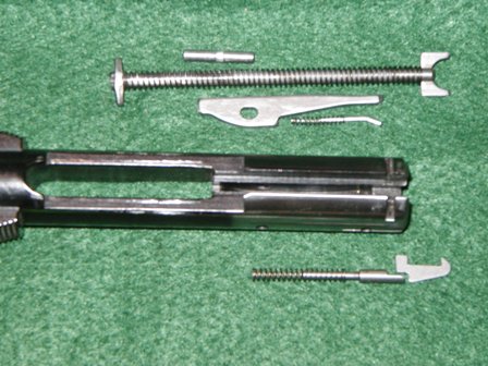
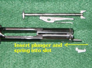
The extractor parts are completely removed. Note - If you've used the bolt disassembly procedures above the bolt is completely stripped as it appears in this picture.
Copyright © Bullseye 2006 - 2013, Guntalk-Online.com, All rights reserved