

22/45 Maintenance Procedures
22/45 Mark III Field Stripping
Disassembly Procedure
(click on picture to enlarge)
| Step 1 | Verify the pistol is unloaded. Open the bolt and inspect the Pistol's chamber and verify it is empty. |
|
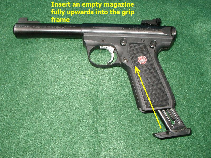
| Step 2 | Insert an empty magazine upward into the grip frame of the pistol. |
 |
| Step 3 | Squeeze the trigger, listen for the hammer to "click". Note - Hammer must be in the fully up or "uncocked" position to proceed with the disassembly. Also the pistol's internal locking screw must be turned with the key until the locking screw is fully flush with the mainspring body in order to remove Mainspring Housing. (Picture here) |
 |
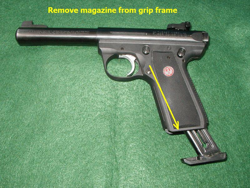
| Step 4 | *IMPORTANT - Remove magazine from the grip frame before attempting to unlatch the mainspring housing. The latch will not fully open if this step is omitted. |
 |
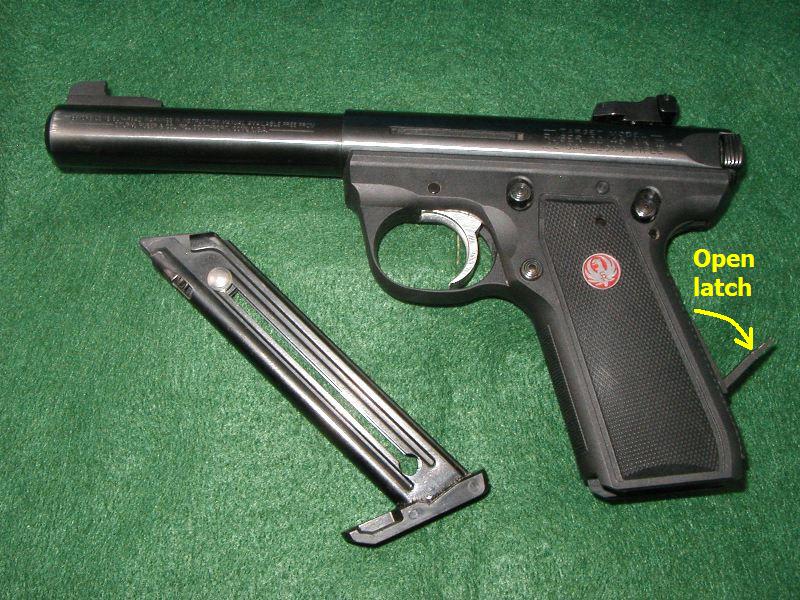
| Step 5 | Open the mainspring latch on the rear of the grip frame |
 |
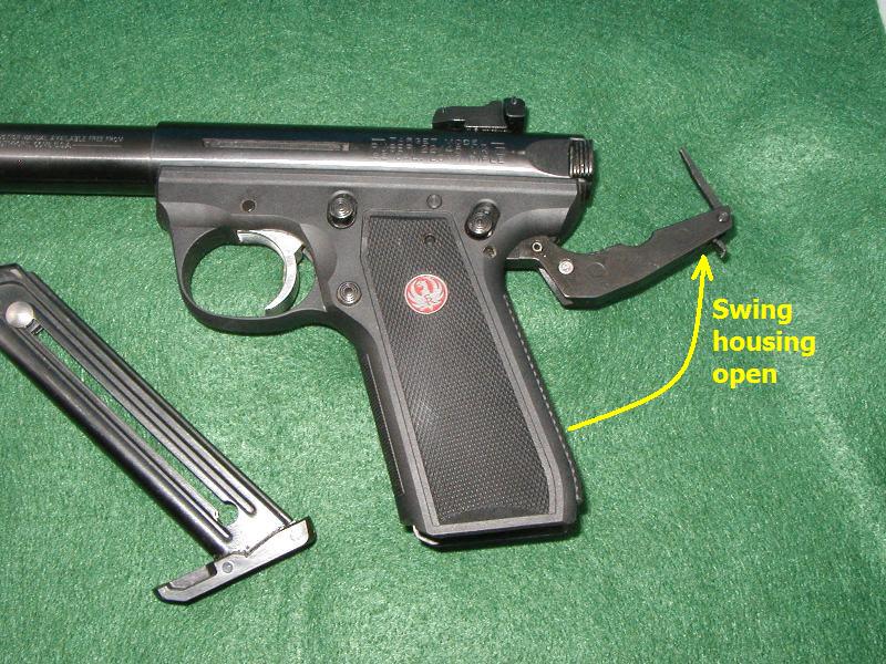
| Step 6 | Next swing the mainspring housing out of the frame well. |
 |
| Step 7 | Pull mainspring housing downwards to remove the bolt stop pin from the recevier and to remove the entire mainspring assemby from the frame. |
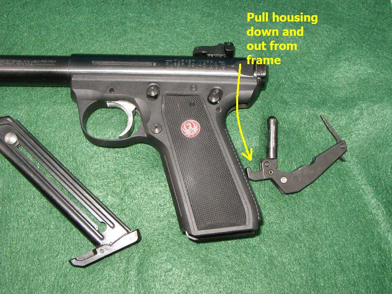 |
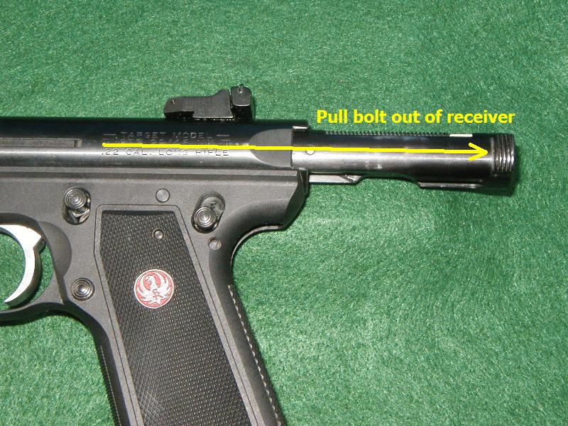
| Step 8 | Pull bolt rearwards until it is clear of the receiver. Note - Hammer will now be in the down or fully cocked position. |
 |
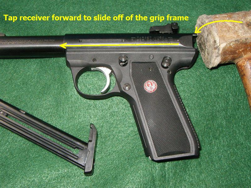
| Step 9 | Slide pistol's receiver forward until it separates from the grip frame. (tap receiver with a mallet if necessary.) |
 |
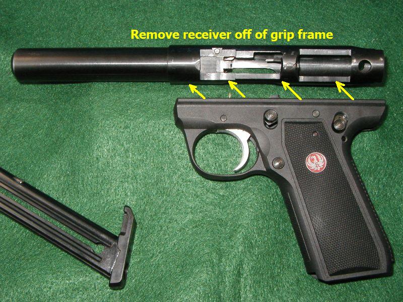
| Step 10 | Pistol is now field stripped for cleaning or other maintenance. |
 |

22/45 Mark III Field Stripping
Reassembly Procedure
(click on picture to enlarge)
Step 1 |
Slide pistol's receiver rearwards until it mates on the grip frame. (tap receiver with a mallet if necessary.) |  |
| Step 2 | The rear lug alignment holes must be aligned between the receiver and the grip frame. Installing the mainspring's bolt stop downward, through the top of the receiver, can help with aligning the frame and receiver properly. You man need to shift the receiver slightly to get the bolt stop to fully seat downward until it touches the top of the receiver. | 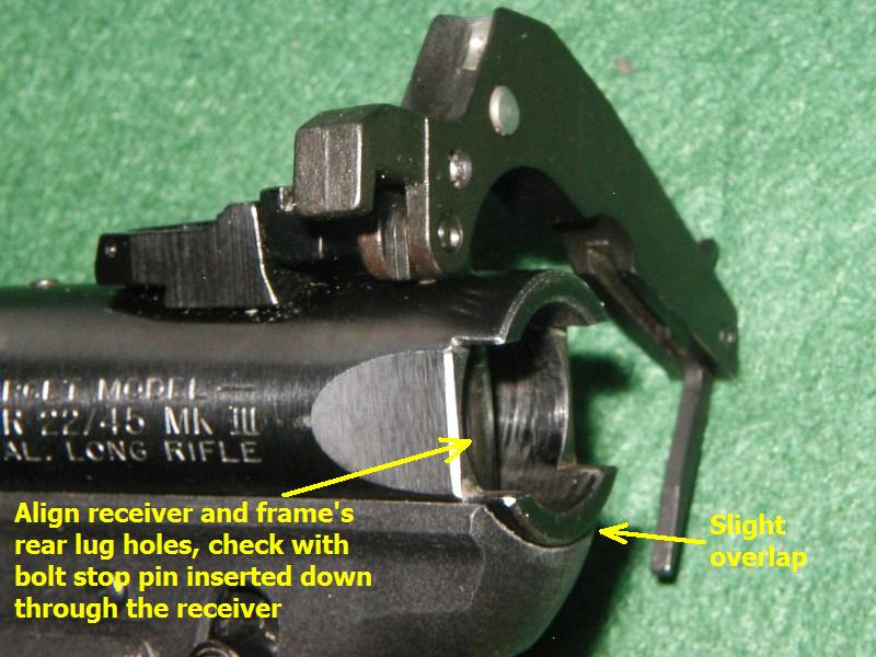 |
Step 3 |
Look into the rear of the receiver and ensure the hammer is in the down or fully cocked position. If the hammer is in the "up" position, the bolt will not insert for reassembly. | 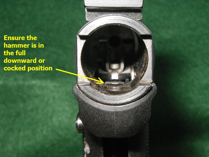 |
Step 4 |
Install bolt into the receiver. Ensure the firing pin stop is in place before inserting the bolt all the way home. Note - You may have either a solid or a hollow firing pin stop pin. | 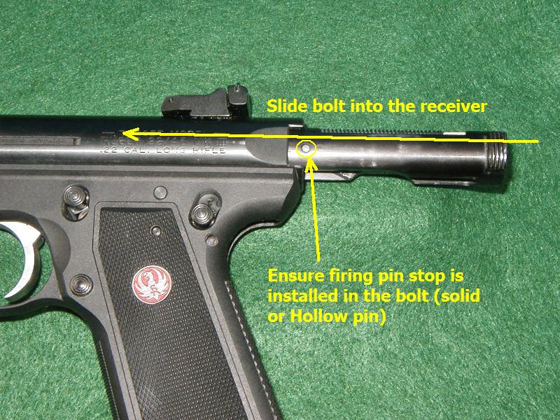 |
Step 5 |
Flip the pistol upside down, insert an empty magazine into the grip frame, squeeze the trigger and and hold it, move the hammer fully forwards with a tool. | 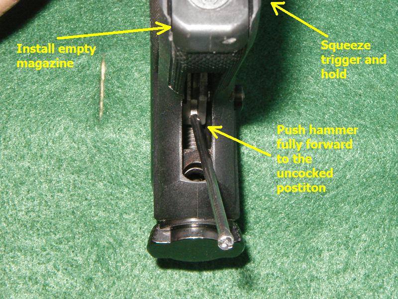 |
Step 6 |
Lay the pistol on its side and install the bolt stop pin upwards, seating it fully into the receiver. Note - The round pin top should be visible at the top of the pin hole. | 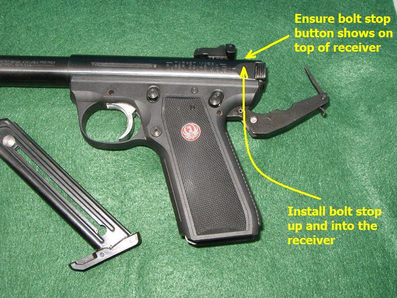 |
Step 7 |
Turn the pistol back upside down and tilt the grip slightly rearwards, allow the hammer strut to ride on the front edge of the mainsping housing as you slowly close it. Note - The hammer strut must remain on the mainsping cap to operate properly. If the hammer strut slips off the cap, then simply reopen the mainspring housing and try closing it again. | 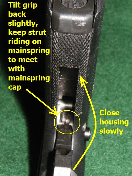 |
Step 8 |
Lay pistol on the side with the mainspring housing almost closed and remove the magazine from the grip frame. Note - If you leave the magazine inserted, the mainspring latch lever will not fully close. | 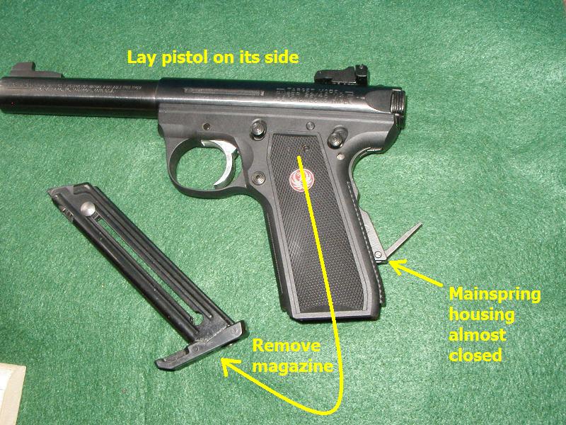 |
Step 9 |
Close mainspring latch lever fully. |  |
Step 10 |
Install an empty magazine and cycle the bolt rearwards a few times. Note - if the bolt only cycles part way the hammer strut likely slipped off of the mainspring cap during the closing of the mainspring assembly or latch. | 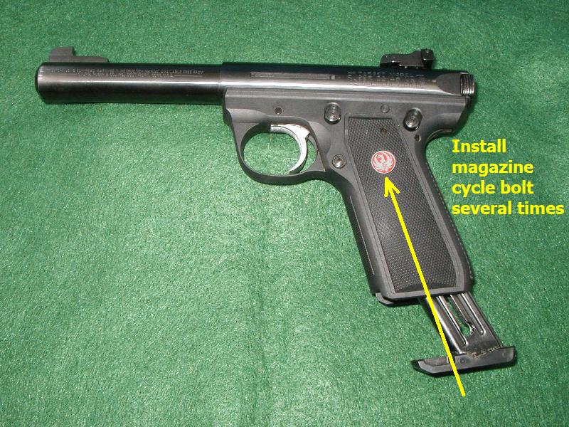 |
Step 11 |
Squeeze trigger and hammer should fall normally. Field stripping maintenance procedure is now completed. |  |
22/45 Mark III Detailed Stripping
Disassembly Procedures
(click on picture to enlarge)
Step 1 |
Field strip Mark III pistol following all proper precautions. Set grip frame up in a clean uncluttered work area. |  |
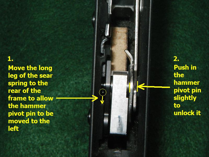
Step 2 |
First, slide sear spring to rear of frame and hold it there. Next, slightly push hammer pivot pin in to the right, towards the left side of the frame. NOTE - As of June 2007 Ruger has replaced the hammer pivot pin with a new one to prevent frame damage. To see this new pin click (HERE) This pin installs in the same manner as the old one. |
 |
Step 3 |
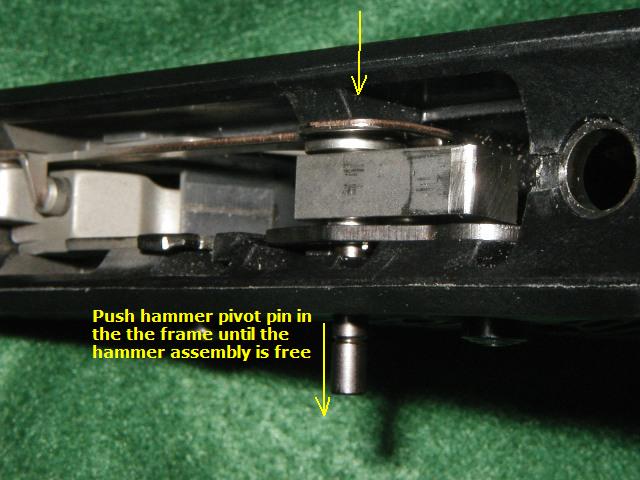
Push the hammer pivot pin to the left just far enough until the hammer assembly is able to swing free. | 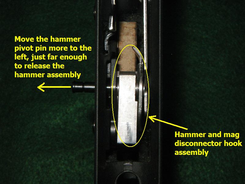 |
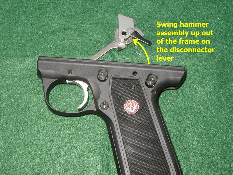
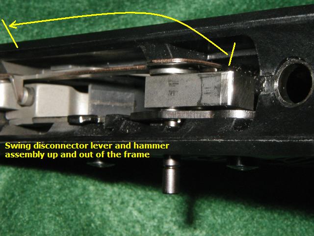
Step 4 |
Swing the hammer and the disconnector lever forward and up and out of the pistol's frame. Remove the hammer and the hammer bushing from the disconnector lever and set it aside. Note- Take care to place the trigger return plunger and trigger return spring aside too, or they may fall out of the frame during the rest of the procedure. |
 |
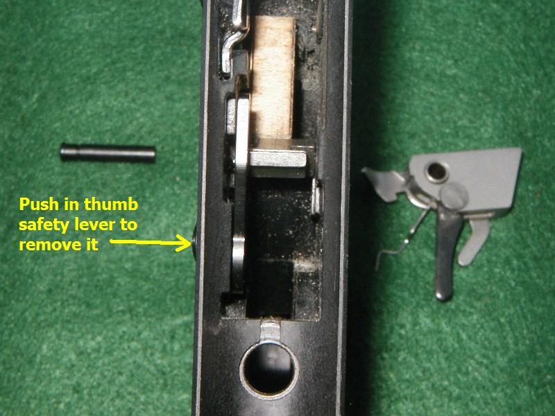
Step 5 |
Pull the hammer pivot pin out of the left side of the frame and remove the thumb safety lever. Set these parts aside for later. Note- the thumb safety lever has two very small parts in it that can drop out of the assembly and get lost. A powerful magnet can help aid in the recovery of these parts, if they fall out of the lever and on to the floor. |
 |
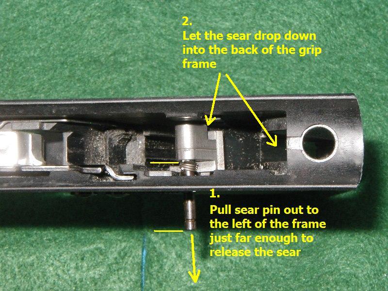
Step 6 |
Now push the sear pivot pin in from the right just far enough to allow the sear to drop back into the mainspring well of the grip frame. Then turn the frame over and shake out the sear. Place sear on the side for later. Once the sear is free, push (or pull) the sear pivot pin completely out through the left side of the grip frame. |
 |
Step 7 |
Last, pull the sear spring up and out of the grip frame assembly. | 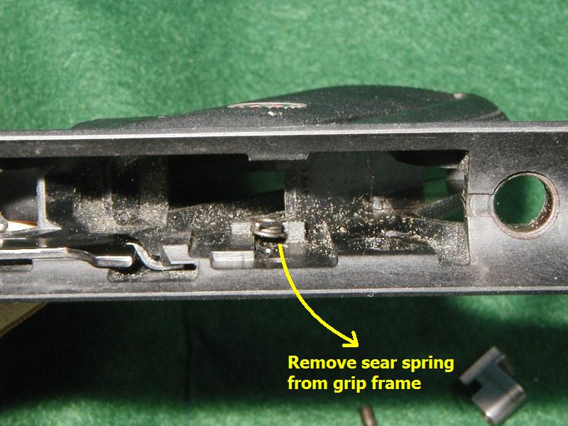 |
Step 8 |
You have now detail stripped the internals of the 22/45 pistol. |  |
22/45 Mark III Detailed Stripping
Reassembly Procedures
(click on picture to enlarge)
Step 1 |
Install the sear spring into the grip frame with the long leg positioned forward and the small leg facing inward and to the rear. | 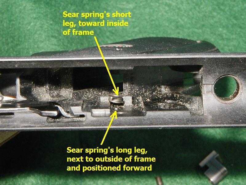 |
Step 2 |
Install the sear pivot pin from the left side of the frame with the groove on the left side, place it in just far enough to hold the sear spring in place. |  |
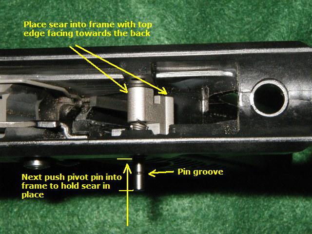
Step 3 |
Insert the sear into the frame and slide the sear pivot pin into the frame to hold the it in place. Just let the sear hang in the frame with the top edge facing rearwards.
|
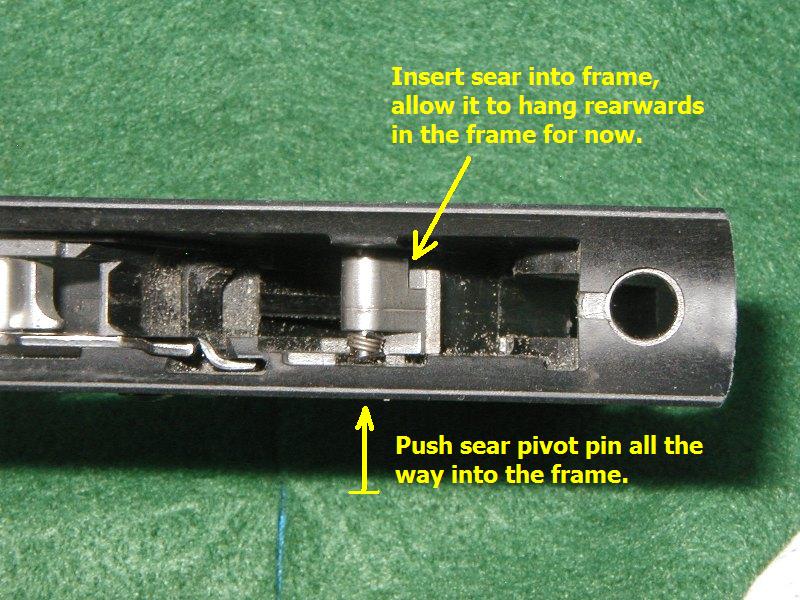 |
Step 4 |
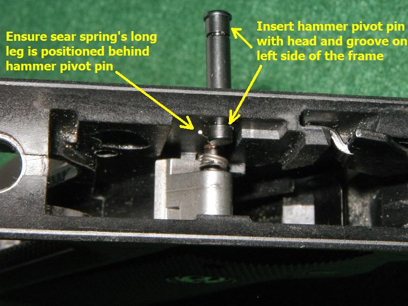
Insert the hammer pivot pin into the frame slightly with the groove positioned on the left side. Now take the long leg of the sear spring and push it to the rear and hold it there. Push the hammer pivot pin in from the left a little bit to hold the long leg of the sear spring in place. NOTE - See the new hammer pivot pin (HERE) This pin installs exactly the same as the old one. Be sure to install the head end (with the pin groove) on the left side of the pistol. |
 |
Step 5 |
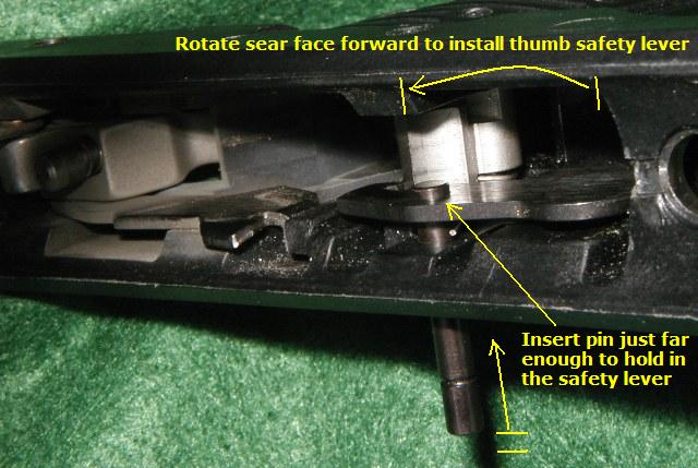
Rotate the sear face to the front of the pistol and hold it there. Place in the thumb safety lever and rotate it forward to hold the sear in place. Slide the hammer pivot pin in from the left a little farther to hold the thumb safety and sear in position. Note - Ensure the detent ball and spring are present in the safety lever. |
 |
Step 6 |
Place the hammer and bushing into the disconnector lever and rotate the entire group back and down into the grip frame. | 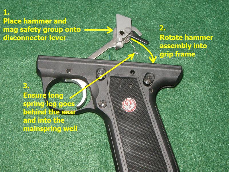 |
Step 7 |
Push the hammer pivot pin in from the left until the pin is flush with the side of the grip frame and you hear a click of the spring in the groove. | 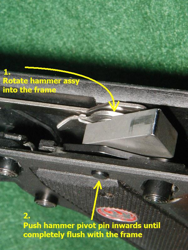 |
Step 8 |
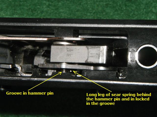
The long leg of the magazine disconnector safety must be postitioned behind the sear and extends down into the mainspring housing well. | 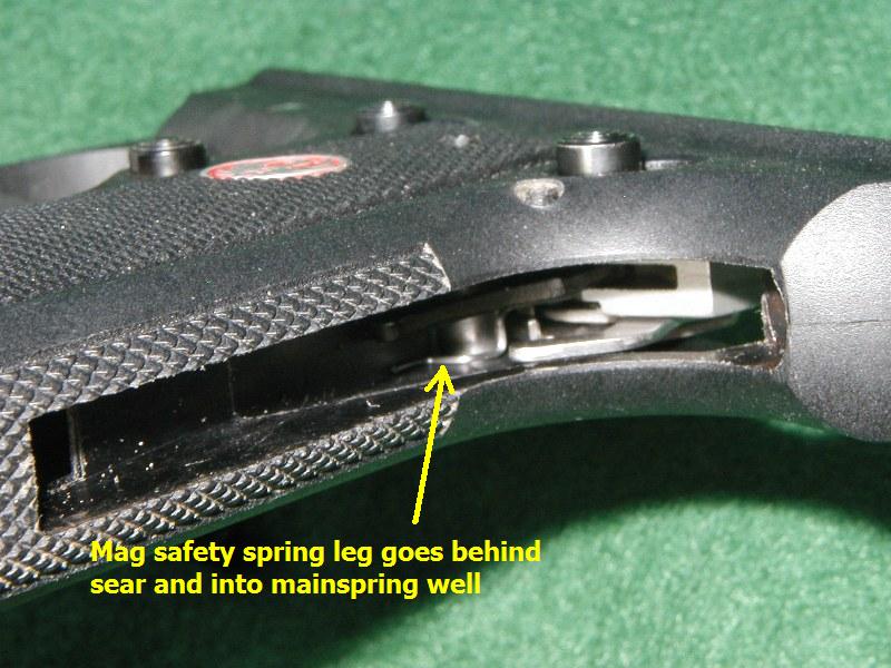 |
Step 9 |
A properly installed hammer will have the groove showing and the long leg of the sear spring to the rear, and seated firmly in the pin's groove. Note - If the pin in not seated, push the head of the hammer pivot to the right and simultaneously press the hammer and safety assembly to the left until you hear a "click" sound. |
 |
Step 10 |
Congratulations! You've reassembled the pistol from detail stripping. Now reinstall your 22/45 receiver and mainspring according to the normal field stripping reassembly procedures. | 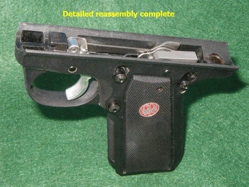 |
22/45 Mark II Detailed Stripping
Disassembly Procedures
(click on picture to enlarge)
Step 1 |
First, remove Receiver from the frame as per normal field strip procedures. Next, slide sear spring to rear of frame and hold it there. Last, slightly push hammer pivot pin in to the right, towards the left side of the frame. | 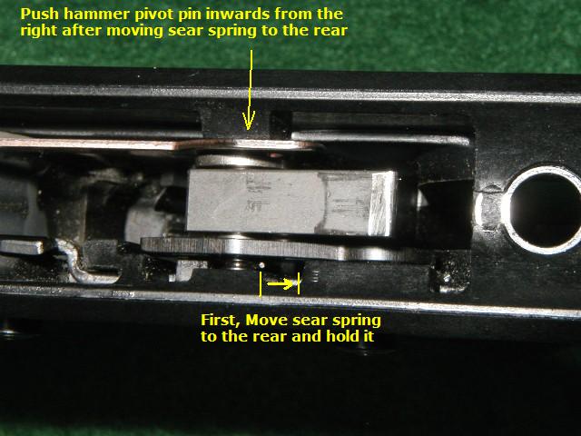 |
Step 2 |
Push the hammer pivot pin to the left just until the hammer assembly is able to swing free. NOTE - As of June 2007 Ruger has replaced the hammer pivot pin with a new one to prevent frame damage. To see this new pin click (HERE) This pin installs in the same manner as the old one. |
 |
Step 3 |
Swing the hammer and the disconnector lever forward and up and out of the pistol's frame. Remove the hammer and the hammer bushing from the disconnector lever and set it aside. Note- Take care to place the trigger return plunger and trigger return spring aside too, or they may fall out of the frame during the rest of the procedure. |
 |
Step 4 |
Pull the hammer pivot pin out of the left side of the frame and remove the thumb safety lever. Set these parts aside for later. Note- the thumb safety lever has two very small parts in it that can drop out of the assembly and get lost. A powerful magnet can help aid in the recovery of these parts, if they fall out of the lever and on to the floor. |
 |
Step 5 |
Now push the sear pivot pin in from the right just far enough to allow the sear to drop back into the mainspring well of the grip frame. Then turn the frame over and shake out the sear. Place sear on the side for later. |  |
Step 6 |
Push or pull the sear pivot pin out through the left side of the grip frame. | 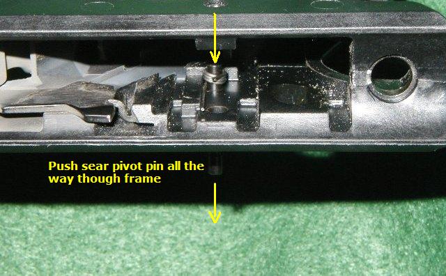 |
Step 7 |
Last, pull the sear spring up and out of the grip frame assembly. You have now detail stripped the internals of the 22/45 pistol. | 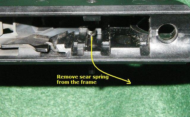 |
22/45 Mark II Detailed Stripping
Reassembly Procedures
(click on picture to enlarge)
Step 1 |
Install the sear spring into the grip frame with the long leg positioned forward and the small leg facing inward and to the rear. | 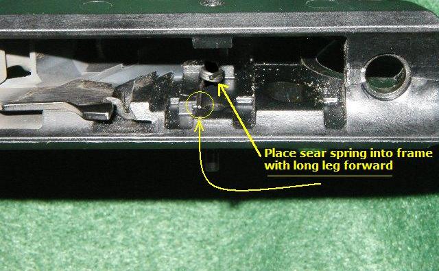 |
Step 2 |
Install the sear pivot pin from the left side of the frame with the groove on the left side, place it in just far enough to hold the sear spring in place. | 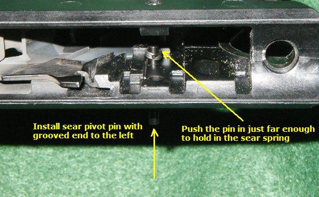 |
Step 3 |
Insert the sear into the frame and slide the sear pivot pin into the frame to hold the it in place. Just let the sear hang in the frame with the top edge facing rearwards. NOTE - See the new hammer pivot pin (HERE) This pin installs exactly the same as the old one. Be sure to install the head end (with the pin groove) on the left side of the pistol. |
 |
Step 4 |
Insert the hammer pivot pin into the frame slightly with the groove positioned on the left side. Now take the long leg of the sear spring and push it to the rear and hold it there. Push the hammer pivot pin in from the left a little bit to hold the long leg of the sear spring in place. | 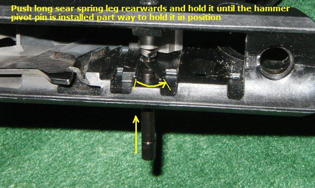 |
Step 5 |
Rotate the sear face to the front of the pistol and hold it there. Place in the thumb safety lever and rotate it forward to hold the sear in place. Slide the hammer pivot pin in from the left a little farther to hold the thumb safety and sear in position. Note- Ensure the detent ball and spring are present in the safety lever. |
 |
Step 6 |
Place the hammer and bushing into the disconnector lever and rotate the entire group back and down into the grip frame. Push the hammer pivot pin in from the left until the pin is flush with the side of the grip frame and you hear a click of the spring in the groove. | 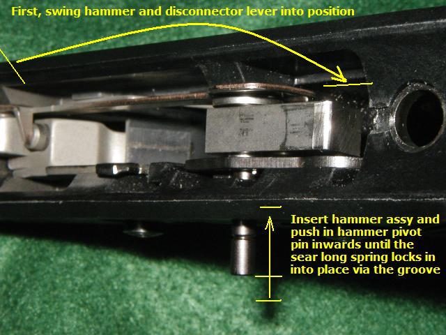 |
Step 7 |
A properly installed hammer will have the groove showing and the long leg of the sear spring to the rear and firmly in the pin's groove. Congratulations! You've reassembled the pistol from detail stripping. Now reinstall your 22/45 receiver and mainspring according to the normal field stripping reassembly procedures. |
 |
Trigger Removal Procedures
(click on picture to enlarge)
Step 1 |
First lift up (rotate) the disconnector lever assembly. |  |
Step 2 |
Press down on the trigger pin locking spring at a point near the trigger and hold it down. At the same time push the trigger pivot pin to the left slightly. This will move the pin beyond the locking groove on the pin and the hold on the locking spring can now be released. | 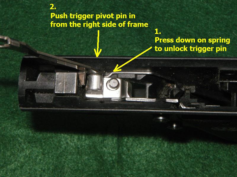 |
Step 3 |
Remove the trigger return plunger off of the top of the trigger block and set it aside. Push (or pull) the trigger pin completely out of the grip frame. | 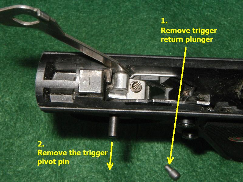 |
Step 4 |
Lift the trigger and disconnector lever out of the frame . |  |
Step 5 |
Separate the trigger and disconnecor by placing the trigger on its left side and lifting the disconnector lever off of the trigger. Trigger Removal is now complete | 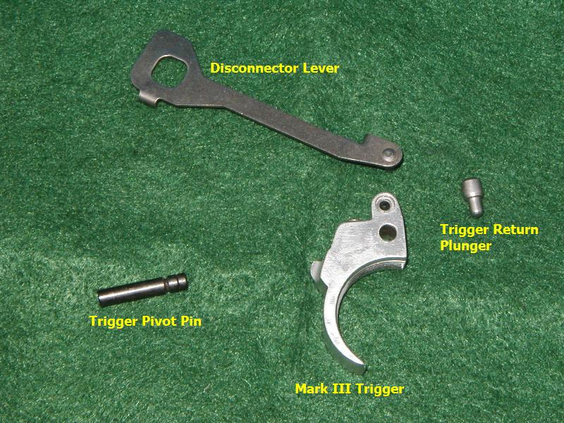 |
Trigger Installation Procedures
(click on picture to enlarge)
Step 1 |
Place the disconnector lever onto the trigger by aligning the disconnector's pivot pin with the upper hole in the trigger. The trigger should move freely on the disconnector. |  |
Step 2 |
Install the trigger and disconnector assembly into the frame. | 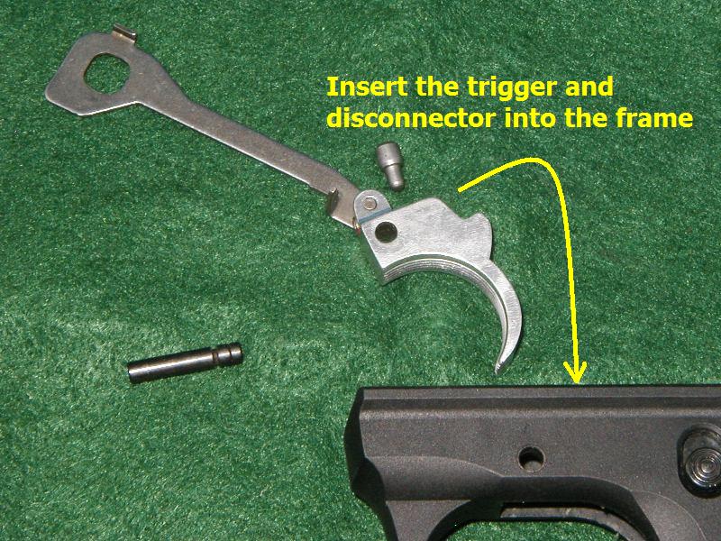 |
Step 3 |
Insert the trigger pivot pin into the left side of the grip frame. Take care to align the trigger and bolt stop pivot loop. Note - Ensure that the trigger pivot pin's locking groove is facing the right side of the grip frame. | 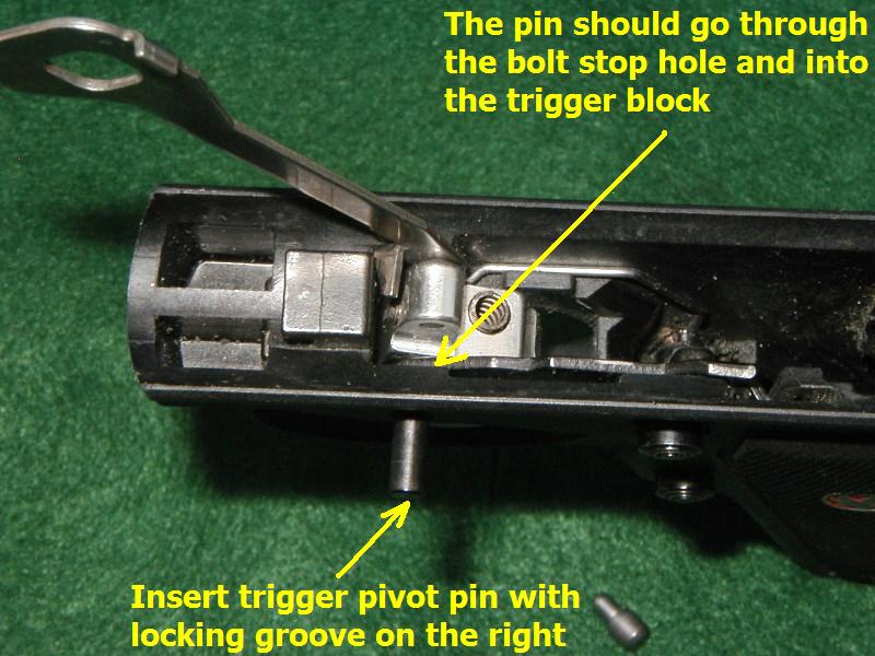 |
Step 4 |
Push the trigger pivot pin completely into the frame until the pin locks into place by the locking spring. Place the trigger return plunger on top of the trigger block. |  |
Step 5 |
Rotate the disconnector lever downwards. Ensure the trigger return plunger stays in position. | 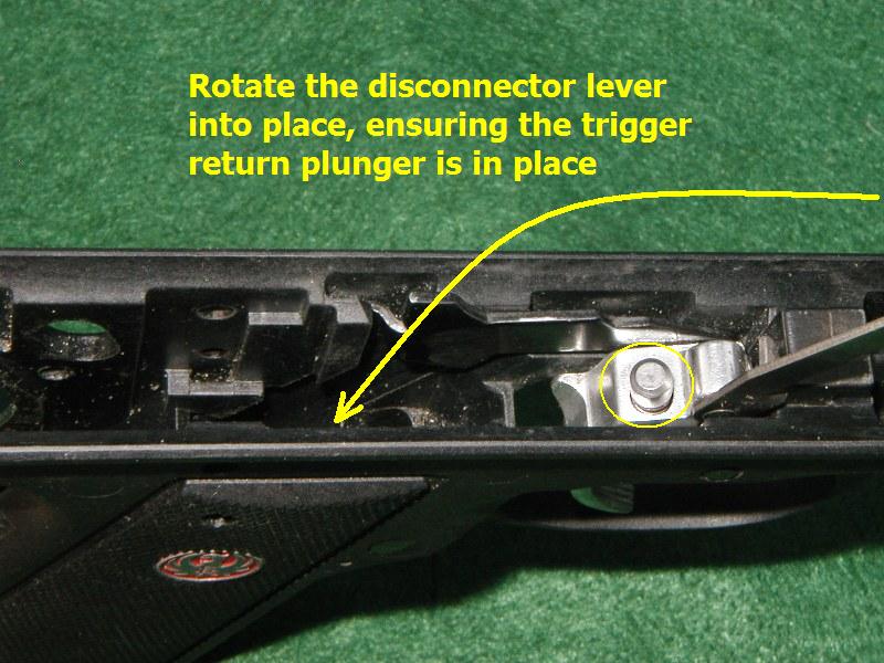 |
Bolt Latch Slingshot Modification
(click on picture to enlarge)
Step 1 |
Remove the trigger assembly using the trigger removal procedures above. Next rotate the front of the bolt stop lever downwards into the frame's trigger well. The back side of the bolt stop lever will now be rotated out of the slot that holds it captive in the frame. The entire bolt stop lever can now be removed from the grip frame . | 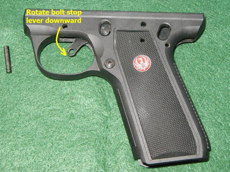 |
Step 2 |
The detent ball and spring is removed from the bolt stop lever. Replace the lever into the frame. The lever will now operate by gravity, just like a Mark III's bolt stop does, and can be released by simply retracting the bolt a released (Slingshot Method). | 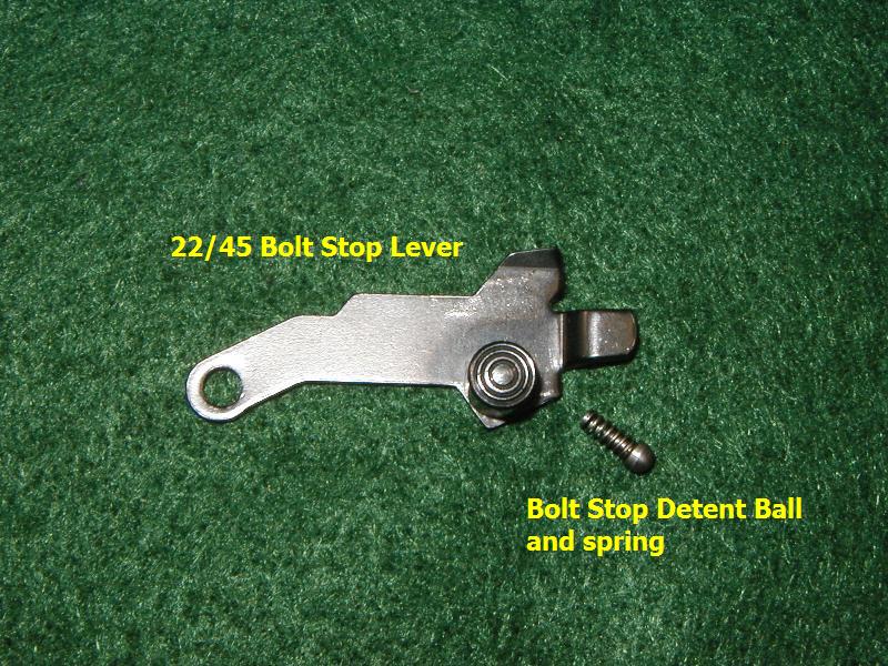 |
Rear Sight Base Removal Procedures
(click on picture to enlarge)
Step 1 |
Loosen the rear sight hold down screw with a small straight slotted screwdriver. Remove the screw completely from its hole. Add a few drops of penetrating oil to the hold down screw hole and let it settle into the sight mount. Clamp the receiver into a well padded vise. Use a brass punch and a medium sized hammer to drift the sight base off the receiver in the direction indicated by the arrow, from the left side of the receiver to the right (ejection port) side. | 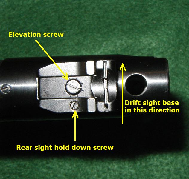 |
Step 2 |
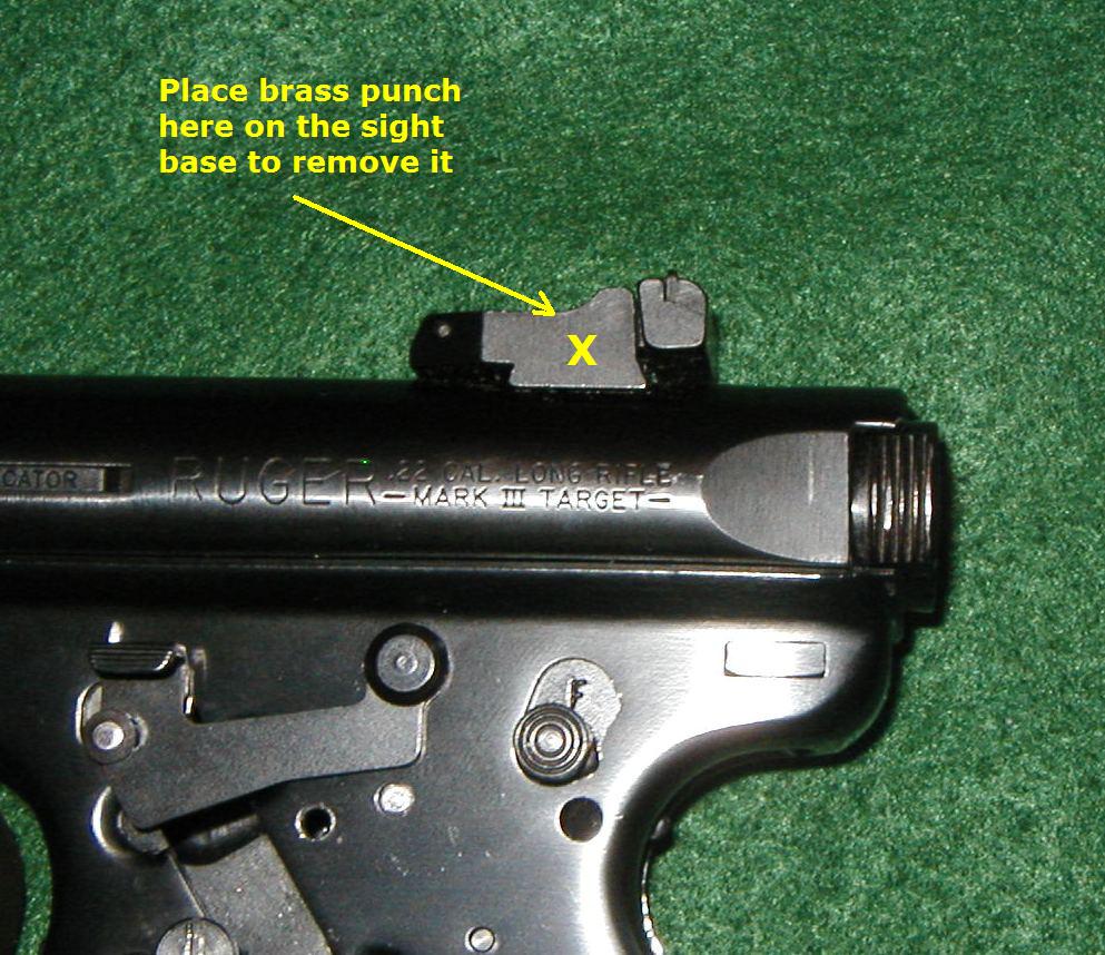
This view shows where to place the punch for maximum energy transfer for drifting the base out of the Ruger's receiver. It may take some effort to get the base to start moving. Take care not to let the hammer slip and mar the finish of the pistol. Once the sight base begins to move, it will come out with several relatively light taps with the hammer. |
 |
Step 3 |
Reinstall the new base from the right (ejection port) side using the same methods described for removal. Tap the base over into position with several light taps using the brass punch and hammer. Degrease the sight hold down screw and hole. Replace the screw and add a little blue Locktite to the threads to secure it into place. | 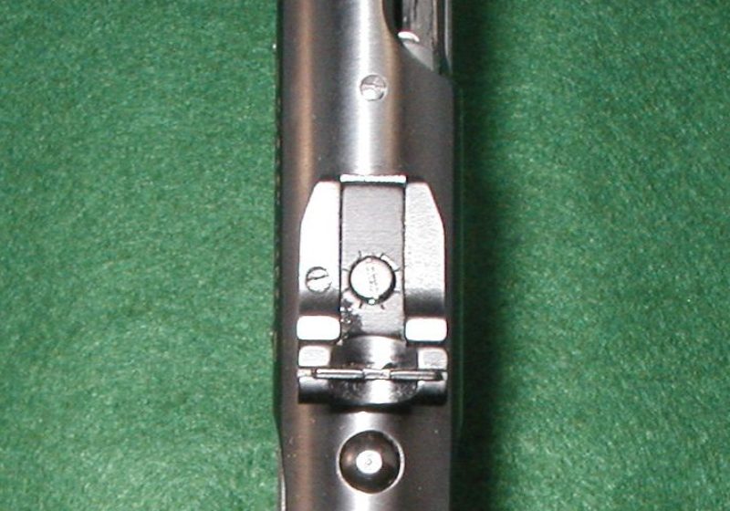 |
Sight Blade Installation Procedures
(click on picture to enlarge)
Step 1 |
You can use two different tools for this task. One is a 3/32" pin punch and the other is a 3/32" Allen wrench. There is a little bit of a trick to installing the sight blade. You must remove the windage screw to complete this installation. If you look at the sight base very closely, you'll notice a small semi-circular cut-out in the front edge of the blade groove. The front edge of your blade has a staked in dimple that fits into that cut-out when the blade is installed. |
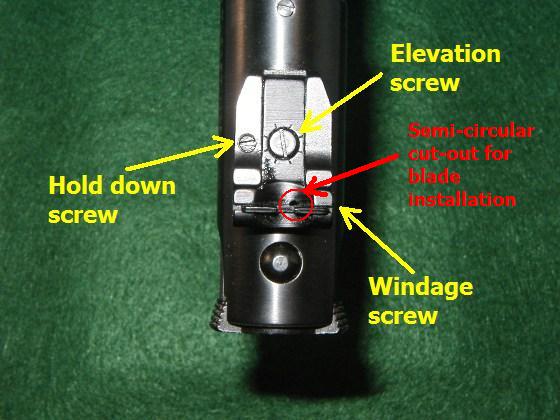 |
Step 2 |
This is a concept view of how all the rear sight parts will fit together when installation is complete . |  |
Step 3 |
Align the front edge of the sight blade's staked in dimple so that it fits into that semi-circular cut-out of the sight base. Place the blade into the slot. It will sit on top of the sight blade return spring. | 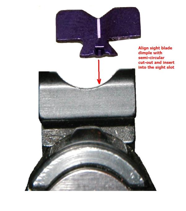 |
Step 4 |
Take your 3/32" tool and insert it into the empty windage screw hole. Push the tool as far to the left as possible; you will be compressing the spring. | 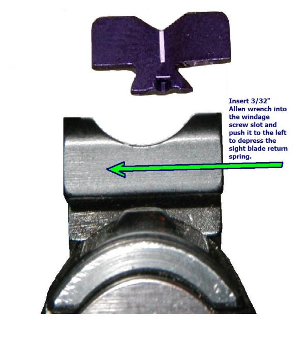 |
Step 5 |
This next step is counter intuitive for this procedure - Tilt the right side of the blade down a little and lightly force it against the 3/32" tool. Now press the top of of the entire sight blade lightly down onto the tool. |  |
Step 6 |
Pull the tool back (to the right) from the windage screw hole and the sight blade will pop into place. | 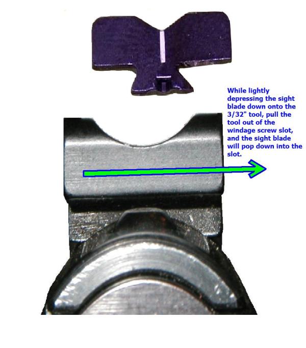 |
Step 7 |
Reinstall the windage screw and you're done. | 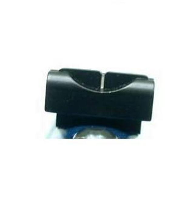 |